This is part of a series of posts analysing the Chip-8 interpreter on the RCA COSMAC VIP computer. These posts may be useful if you are building a Chip-8 interpreter on another platform or if you have an interest in the operation of the COSMAC VIP. For other posts in the series refer to the index or instruction index.
INSTRUCTION GROUP: AMMM
Load I with the address 0MMM
INSTRUCTION GROUP: FX1E
Add the value in VX to the index variable I
All memory access in a Chip-8 programme is achieved through an index variable I. This is effectively an alias for the CDP1802 register RA. The full width of this register is used, so I is ostensibly a 16-bit variable. However, only 12 bits are needed to address the maximum 4K of on-board memory available on the COSMAC VIP.
In an earlier post I showed how the index variable I could be loaded with any 12-bit address using the AMMM instruction group, and how it is used to provide the location for saving variables to memory and loading them back again.
In another post I showed how I is used to index sprites stored in memory when these are drawn to the display. I is also used to index a set of predefined patterns that form the Chip-8 character set and to indicate where binary coded decimal (BCD) numbers are to be stored. I will look at both of these functions in detail in a future posts.
As well as directly loading I with an absolute 12 bit address, you can also adjust the address by adding an offset. This is achieved with the FX1E instruction group. This instruction adds the value in VX to the value currently stored in I. You might use this, for example, for indexing data in a lookup table. You would set I to the base address of the table using an AMMM instruction, calculate the offset of the required data in VX and then use an FX1E instruction to calculate the correct address within the table.
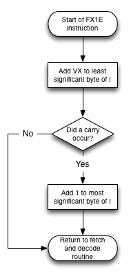
Because this instruction adds an 8-bit value to a 16-bit value, it’s not a straightforward addition. Here’s the flowchart showing the process.

And here’s the code:
Labels | Code (hex) | Comments |
FX1E: | E6 | Set register indirect addressing operations to use R6 (VX pointer). |
011F | 8A | Get the low order byte of I (stored in RA.0). |
0120 | F4 | Add value in VX to low order byte of I. |
0121 | AA | Put result back into low order byte of I (RA.0). |
0122 | 3B 28 | If no carry is generated (i.e. the addition of the offset didn’t cross a page boundary) then there’s nothing more to do. |
0124 | 9A | Get high order byte of I (RA.1). |
0125 | FC 01 | Add 1 to it (to point to next page). |
0127 | BA | Put the result back in high order byte of I (RA.1). |
SAME_PAGE: | D4 | Return to the fetch and decode routine. |
One thing to note about this instruction is that it will quite happily let you sail off into the uncharted waters of memory beyond the on-board 4K, because it will only wrap when the offset takes the address beyond 65535. The Chip-8 programmer must ensure it contains a meaningful value.
The execution times for this instruction are 12 machine cycles (54.48 microseconds) when no page boundary is crossed and 18 machine cycles (81.72 microseconds) when a page boundary is crossed. Because this is part of the FXXX instruction group the overhead for the second stage decoding of these instructions must be added. See this earlier post for details.
The programmer of a contemporary interpreter must include this instruction.
Be First to Comment