This is part of a series of posts analysing the Chip-8 interpreter on the RCA COSMAC VIP computer. These posts may be useful if you are building a Chip-8 interpreter on another platform or if you have an interest in the operation of the COSMAC VIP. For other posts in the series refer to the index or instruction index.
In this post I’m taking a break from analysing the Chip-8 interpreter so I can look at the interrupt routine in the operating system. This is a convenient point to take this detour as several of the Chip-8 instructions still to be covered are affected by the interrupt routine.
In an earlier post I discussed how the video circuitry is enabled during the Chip-8 initialisation sequence.
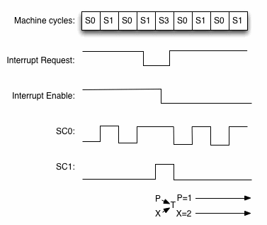
On the COSMAC VIP the interrupt mechanism is used by the CDP1861 video display interface to indicate when it wants to begin a display cycle. Normally the 1802 will execute two machine cycles for each instruction: a fetch cycle and an execute cycle. The processor indicates which cycle it is in by setting or resetting two state control lines (SC0 and SC1). The possible states for these lines is shown below:
Cycle | Label | SC1 | SC0 |
Fetch | S0 | 0 | 0 |
Execute | S1 | 0 | 1 |
DMA | S2 | 1 | 0 |
Interrupt | S3 | 1 | 1 |
There are a few instructions that require three machine cycles (they have an additional S1 cycle), but these instructions cannot be used when interrupts are enabled. When the 1861 is ready to start a display cycle it pulls the Interrupt control line low to indicate an interrupt request to the 1802. This will be honoured, provided the interrupt enable flip flop is set.
When the 1802 receives the request it waits until the S1 cycle for the current instruction has been completed and then it enters an interrupt response cycle (S3). Several things happen at this point:
- the interrupt enable flip flop is reset (this prevents further interrupts from occurring while the current interrupt is being serviced)
- the interrupt is acknowledged by setting the two state code control lines high
- the 1802 saves the program counter (P) and indirect register addressing (X) registers in a temporary register (T)
- it then sets P to 1 and X to 2.
Normal service is then resumed with the execution of the next S0 cycle. However, note that what is now being executed is the interrupt service routine pointed to by R1. This is shown in the diagram below.
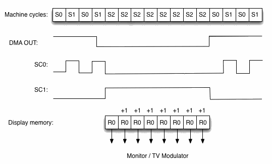
Although the 1861 uses interrupts to indicate to the 1802 that it is about to refresh the display, it uses direct memory access (DMA) to actually read the display memory. When it is ready to display a row of pixels, the 1861 takes the DMA-OUT control line low. When the 1802 receives this signal it waits until the current instruction has finished executing (the end of the S1 cycle) and then enters an S2 DMA cycle. The 1802 will execute DMA cycles until the DMA-OUT line goes high again. The 1861 will use this feature to execute 8 DMA cycles to read an entire line of pixels (8 bytes, which is 64 pixels). During a DMA cycle the following happens:
- the 1802 acknowledges the DMA transfer by setting SC0 low and SC1 high
- the address in R0 is placed onto the address bus and a memory read is requested
- the memory responds by placing the required byte on the data bus
- the 1861 reads the byte from the data bus and uses the data to drive the display (displaying a sequence of 8 pixels)
- R0 is incremented.
This is shown in the diagram below:
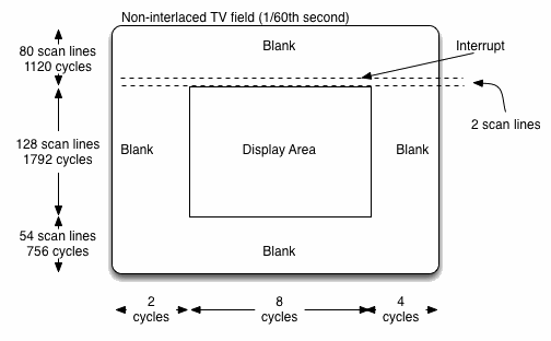
The COSMAC VIP supports a maximum screen size of 128 pixels high by 64 pixels wide. Left to its own devices the 1861 will quite happily display the 1024 bytes starting at whatever address is in R0. In an earlier post I said that the screen size for Chip-8 programmes was only 32 pixels high by 64 pixels wide. So what happens to the other 96 vertical pixels? The answer is that all 128 rows are shown, but the pixel data is only changed after every four rows. Effectively each row of pixels is drawn four times. Although you might think this would result in tall and narrow pixels, in fact the pixels at the maximum screen size are long and thin, so drawing each row four times has the effect of making the pixels more square.
To understand how each line gets drawn four times, it is necessary to look at what happens when the screen is being refreshed. The clock frequency of the COSMAC VIP (1.76064 Mhz) is not arbitrary. It is set so that, at 60 frames per second, a single TV scan line lasts for exactly 14 machine cycles, and a single TV field lasts for exactly 3668 machine cycles. When the scan position is just about to reach the scan line that is two lines above where the display will start, the 1861 generates an interrupt. This gives the COSMAC VIP operating system exactly 29 cycles before the scan position reaches the first scan line on which drawing occurs. During this time the interrupt routine is initialised and is able to take care of some essential housekeeping before the 1861 starts reading display memory. Because the display only occupies the central portion of each scan line, there are two machine cycles at the start of each scan line before the 1861 starts its DMA access. The DMA access requires eight machine cycles. Then there are a further a further four machine cycles until the end of the scan line. The COSMAC VIP operating system uses this time to reset R0 to the start of the current row of pixels. It does this three times so that the same row of pixels is displayed four times on successive scan lines. This is illustrated in the diagram below:
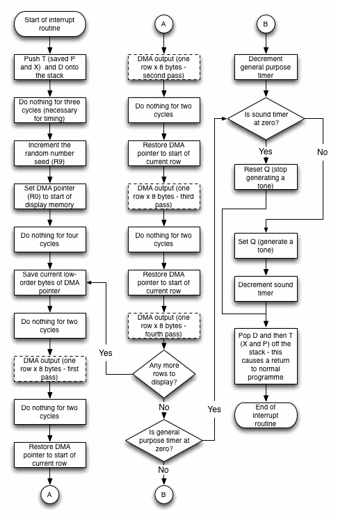
A flowchart for the interrupt routine is shown below:
Here is the code for this part of the operating system:
Labels | Code (hex) | Comments |
TURN_ Q_ OFF: | 7A | Reset Q. This stops the COSMAC VIP from generating a tone. |
RETURN_ FROM_ INTERRUPT: | 42 | Pop the saved value of the accumulator off the stack |
8145 | 70 | Return from the interrupt routine. This works by popping the saved value of the T register and using this to restore P and X. It also re-enables interrupts. |
INTERRUPT_ ROUTINE: | 22 | This is the entry point for the interrupt routine. |
8147 | 78 | Push T onto stack (This is a temporary register that stores the values of P and X at the point the interrupt occurred). |
8148 | 22 | Decrement stack pointer ready for a push. |
8149 | 52 | Push the accumulator onto the stack. |
814A | C4 | Do nothing for three cycles (required for timing the screen refresh correctly). |
814B | 19 | Increment the random number seed (R9). |
814C | F8 00 | This will form the low-order byte of the DMA address for the screen refresh. |
814E | A0 | Load this into the DMA pointer (R0). |
814F | 9B | Get the high-order byte of the display memory address. |
8150 | B0 | Load this into the DMA pointer (R0). The DMA pointer now points to the first byte of the display memory. |
8151 | E2 | X is already 2, so this is effectively a two machine cycle NOP. Again, these are necessary for accurate timing of the screen refresh. |
8152 | E2 | (Two cycle NOP – see note in 8151.) |
DISPLAY_ NEXT_ ROW: | 80 | Get low order byte of current DMA address into accumulator. |
8154 | E2 | (Two cycle NOP – see note in 8151.) 8 DMA cycles occur between this instruction and the next one. (During these cycles the CDP 1861 video interface reads a single row of pixels in the display memory and outputs it to the monitor, or to a TV via a modulator). |
8155 | E2 | (Two cycle NOP – see note in 8151.) |
8156 | 20 | Decrement DMA pointer. This is necessary because the DMA pointer will have advanced to the next page after displaying any of the last four lines of the display. If it has, this will ensure the high order byte is reset to the correct page. |
8157 | A0 | Restore the low-order byte of the DMA pointer (this moves it back to the start of the current pixel row). The second DMA access (8 DMA cycles) occurs between this instruction and the next one. |
8158 | E2 | (Two cycle NOP – see note in 8151.) |
8159 | 20 | Decrement DMA pointer (see note in 8156). |
815A | A0 | Restore DMA pointer (see note in 8157). The third DMA access (8 DMA cycles) occurs between this instruction and the next one. |
815B | E2 | (Two cycle NOP – see note in 8151.) |
815C | 20 | Decrement DMA pointer (see note in 8156). |
815D | A0 | Restore DMA pointer (see note in 8157). The fourth and final 8 DMA cycles for the current pixel row will occur between this instruction and the next one. |
815E | 3C 53 | If there are more rows to display (which is indicated by EF1 being low), branch back to start of loop. |
8160 | 98 | Get the general purpose timer (R8.1). |
8161 | 32 67 | If it’s zero, then we don’t need to do anything with it. |
8163 | AB | Temporarily copy the timer into RB.0 (This is necessary because we can’t decrement the high order byte of R8 directly without using subtraction. This would affect DF, which we need to preserve in case it is needed by the interpreter instructions to be executed after the interrupt). |
8164 | 2B | Decrement it. |
8165 | 8B | Get the new timer value. |
8166 | B8 | Put it back into the general purpose timer. |
CHECK_ SOUND_ TIMER: 8167 | 88 | Get the sound timer (R8.0). |
8168 | 32 43 | If it’s zero, we need to make sure that Q is reset. |
816A | 7B | Set Q (This causes the COSMAC VIP to emit a tone). |
816B | 28 | Decrement the sound timer (Note that we can be sure this will have no inadvertent affect on the general purpose timer at R8.1, because this instruction can only ever be executed if R8.0 is not zero) |
816C | 30 44 | Branch to the instructions that return from the interrupt routine. |
Here’s a summary of the timing of the interrupt routine for all possible conditions:
General purpose timer (R8.0) | Sound timer (R8.1) | Machine cycles |
zero | zero | 807 (3663.78 microseconds) |
zero | non-zero | 811 (3649.5 microseconds) |
non-zero | zero | 815 (3700.1 microseconds) |
non-zero | non-zero | 819 (3718.26 microseconds) |
You need to add the overhead of 1024 DMA cycles (4648.96 microseconds) to these figures. When you consider that the display is refreshed 60 times a second, you can see that almost half of the available CPU time is consumed by servicing the display interrupt and waiting for DMA access to complete!
Note that this routine is also responsible for:
- incrementing the random number seed
- updating the general purpose timer
- updating the sound timer and turning the COSMAC VIP’s tone generator on or off accordingly.
I look at the random number function in more detail here and the sound function here.
Note that, although three-cycle instructions can’t be used when the COSMAC VIP interrupts are enabled, there is a single three-cycle NOP instruction at 0x814A. This is possible because further interrupts are disabled while the interrupt handler is running and it is required because there are an odd number of machine cycles between the start of the interrupt routine and the first DMA request.
A programmer of a modern interpreter probably doesn’t have to work quite so hard to refresh the display, but must, at the very least, update the timers and tone generation sixty times a second.
Be First to Comment