This is part of a series of posts analysing the Chip-8 interpreter on the RCA COSMAC VIP computer. These posts may be useful if you are building a Chip-8 interpreter on another platform or if you have an interest in the operation of the COSMAC VIP. For other posts in the series refer to the index or instruction index.
INSTRUCTION GROUP: DXYN
Draw the N byte sprite stored at the address pointed to by I on the display at location X and Y. Set VF to 0x01 if any set pixel in the sprite overwrites an existing set pixel on the display, otherwise set VF to 0x00.
Chip-8 has only one instruction for getting data onto the display. Fundamentally it works by reading sprite data stored in memory and writing it to the display memory (It’s actually a little more complicated than that, but we’ll get onto that in a moment). Then, when the next interrupt occurs, the display controller will read this memory and draw it to the display as a series of pixels. I analysed the interrupt and screen refresh mechanism in an earlier post.
The draw instruction expects the index register, I, to be pointing to the memory location of the first row of pixels in the sprite. You can set I with either the AMMM instruction, which simply sets I to the address 0x0MMM, or with the FX29 instruction, which I will analyse in a later post.
Each bit in the sprite represents a single pixel. As Chip-8 uses a black and white display, pixels can either be on (1) or off (0). Each row of pixels is stored sequentially.
Chip-8 allows you to set the height of the sprite in the final hex digit of the instruction, so sprites can be between one and 15 pixels high. The width of the sprite is fixed at eight pixels (one byte).
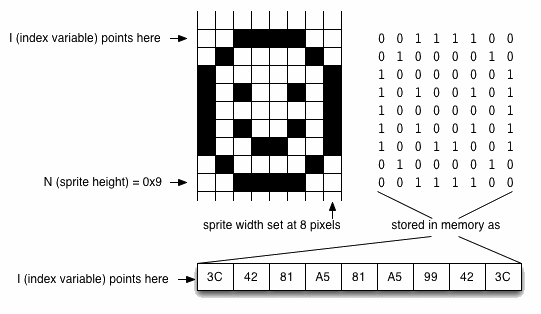
This is not really as restrictive as it sounds. If you want a sprite that is narrower than eight pixels, simply set the unwanted pixels to the right of the image to 0, as shown below:
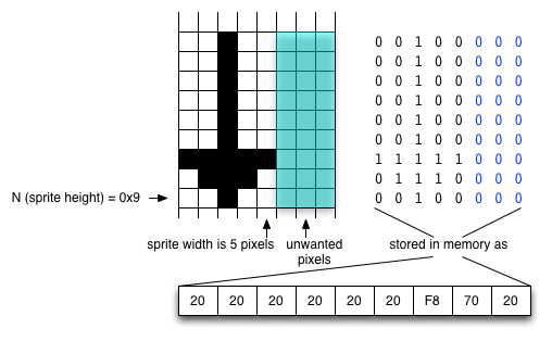
Because of the way Chip-8 sprites are drawn, the unset pixels will have no effect on the display memory. If you want a sprite that is wider than eight pixels and/or higher than 15 pixels, then you should break it into smaller sprites and then draw each part individually, resetting the position appropriately each time. The example shown below assumes a scheme whereby multipart sprites are stored by row starting with the top-left sprite and with all the parts stored consecutively in memory:
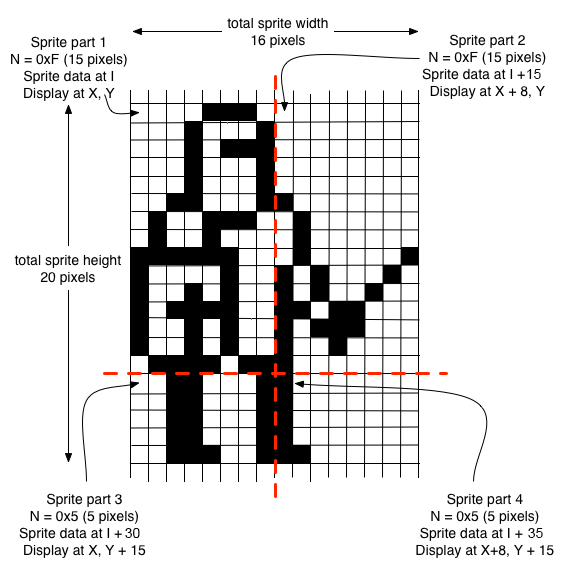
One thing you have to remember if you use this technique is to check for collision after you have drawn each part of the sprite, as the collision flag will only be valid for the part that has just been drawn.
The reason you can have a narrower sprite simply by leaving some columns of pixels blank is because Chip-8 sprites are XOR’d with the current data on screen. So an unset pixel in a sprite will have no effect on the data currently on screen. A set pixel in a sprite will cause the pixel on screen to be set if it is currently unset, or unset if it is currently set. In the latter case, a collision flag will also be set to show the sprite data overlapped with existing data on screen.
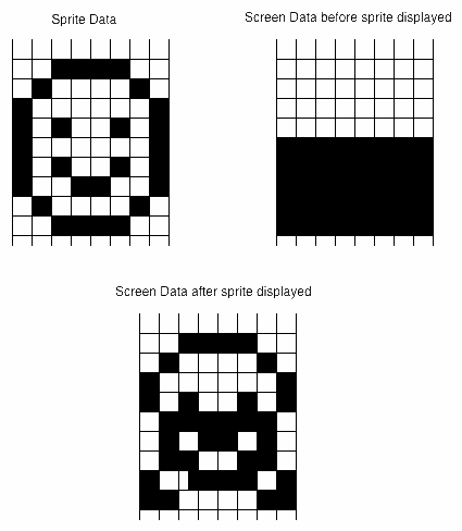
Using this technique, it is possible to erase a sprite simply by re-drawing the same sprite at the same coordinates because drawing the sprite for the second time will unset the pixels that were set by the first drawing and vice versa. Of course in that situation you’d want to ignore the collision flag as the sprite would record a collision with itself.
Here’s the flowchart for the routine that draws sprites:
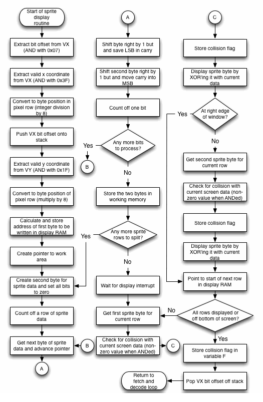
Here’s the code for the sprite drawing routine:
Labels | Code (hex) | Comments |
DRAW_ SPRITE: | 06 | Get VX (stored at address in R6). |
0071 | FA 07 | Mask with 0x07 to save only least significant three bits. These indicate the bit offset of the first bit of sprite data. |
0073 | BE | Save these in RE.1. |
0074 | 06 | Get VX. |
0075 | FA 3F | Mask with 0x3F to save the six least significant bits (max value of X position is 63, which requires only six bits). |
0077 | F6 | The next three instructions perform an integer division of VX by eight, which gives the position in the pixel row of the first byte that will contain sprite data. |
0078 | F6 |
|
0079 | F6 |
|
007A | 22 | Decrement the stack pointer (R2) ready for a push. |
007B | 52 | Push accumulator (containing most significant three bits of VX) onto the stack. |
007C | 07 | Get VY (stored at address in R7). |
007D | FA 1F | Mask with 0x1F to save the five least significant bits (max value of Y position is 31, which requires only five bits). |
007F | FE | The next three instructions perform a multiplication of VY by eight, which gives the position in display memory of the first row that will contain sprite data. |
0080 | FE |
|
0081 | FE |
|
0082 | F1 | OR the result with the top of the stack. This gives the position in display memory of the first byte that will contain pixel data from the sprite. |
0083 | AC | Put the result in RC0. |
0084 | 9B | Get high order byte of address of display memory. |
0085 | BC | Put this in RC1. RC now holds the address of the first byte that will have sprite data written to it. |
0086 | 45 | Get the second byte of the Chip-8 instruction and advance the Chip-8 programme counter. |
0087 | FA 0F | Mask off the least significant hex digit. This contains the number of bytes (rows) in the sprite pattern. |
0089 | AD | Save it in RD – this will be used as a display row counter. |
008A | A7 | Save it in R7 – this will be used as a sprite row counter. |
008B | F8 D0 | 0xD0 is the low order byte of the address of the area of RAM set aside as a Chip-8 work area. This will be used to assemble a two-byte wide copy of the sprite with the sprite data shifted to the correct offset for the position at which the sprite will be displayed |
008D | A6 | Put this into R6.0 As R6 is normally used as the VX pointer and the variables are stored in the same page, R6.1 will already be set correctly. |
NEXT_ SPRITE_ ROW: | 93 | R3.1 is used as a convenient source of the constant 0x0. |
008F | AF | Set RF.0 to 0x0. The right-hand (2nd) byte of the reconstructed sprite will be initially assembled here. |
0090 | 87 | Get the number of rows left to assemble. |
0091 | 32 F3 | Branch to the next stage if they are all done. |
0093 | 27 | Count off one row of sprite data |
0094 | 4A | Get one byte of sprite data from the address pointed at by I (RA) and advance I to next byte. |
0095 | BD | Save this in RD.1. |
0096 | 9E | Get the bit offset for the first bit of sprite data (this was saved in RE.1 earlier). |
0097 | AE | Put these in RE.0. This will be used as a bit counter. |
SPLIT_ SPRITE_ ROW: | 8E | Get the current bit count. |
0099 | 32 A4 | Branch when the bit count is zero, indicating that the sprite data for that row is now correctly split across two bytes (note that this could be immediately if the sprite is positioned at the start of a display memory byte), |
009B | 9D | Get byte to be displayed. |
009C | F6 | Shift right by 1 bit. This will move a zero into the most significant bit, shift everything else along and move the least significant bit into the carry flag. |
009D | BD | Store shifted byte back in RD.1. |
009E | 8F | Get current pattern in second byte. |
009F | 76 | Shift with carry to the right by one bit. This will move the discarded bit from the first byte into the most significant bit position and shift everything else along. |
00A0 | AF | Store the result back in RF.0. |
00A1 | 2E | Count off another bit. |
00A2 | 30 98 | Branch back to top of loop. |
STORE_ SPRITE_ ROW: | 9D | Get lefthand byte of sprite row to be displayed. |
00A5 | 56 | Store it in the working area in memory. |
00A6 | 16 | Point to the next byte in the working area. |
00A7 | 8F | Get the righthand byte of the sprite row to be displayed. |
00A8 | 56 | Store it in the working area in memory. |
00A9 | 16 | Point to the next byte in the working area. |
00AA | 30 8E | Loop back and do the next row. |
DISPLAY_ SPRITE: | 00 | Wait until the next display interrupt has completed (This prevents sprite tearing). |
00AD | EC | Set the pointer to display memory (RC) to be used for register indirect addressing memory operations. |
00AE | F8 D0 | 0xD0 is the low order byte of the address of the area of RAM set aside as a Chip-8 work area. This is where the offset sprite has been assembled. |
00B0 | A6 | R6 now points to assembled offset sprite. |
00B1 | 93 | R3.1 (high-order byte of interpreter programme counter) is a convenient source of the constant 0x0. |
00B2 | A7 | Set R7.0 to zero. This will be used to temporarily store the collision status. |
SPRITE_ DISPLAY_ LOOP: | 8D | Get the number of rows left to display. |
00B4 | 32 D9 | Branch to next stage if all rows done. |
00B6 | 06 | Get the lefthand byte of sprite data. |
00B7 | F2 | AND it with the current byte in display memory at the target position. This will put a 1 in any bit where a set bit overlaps in both the display memory and the sprite data. So any non-zero result indicates that a collision has occurred. |
00B8 | 2D | Count off one row. |
00B9 | 32 BE | Branch forward if no collision occurred. |
00BB | F8 01 | Construct a collision flag. |
00BD | A7 | Store this in R7.0. |
DISPLAY_LEFT_BYTE: | 46 | Get the lefthand byte of sprite data and advance the pointer. |
00BF | F3 | XOR it with the current byte in display RAM. |
00C0 | 5C | Now write it to the display by storing the modified byte back in the display RAM. |
00C1 | 02 | Get the x position of the sprite (in bytes) from the stack. |
00C2 | FB 07 | XOR it with 0x07 to see if it is at position 7 (i.e. the last byte in the row). |
00C4 | 32 D2 | If it is at the right edge of the window, then the second byte would be off screen and there is no point in trying to display it, so skip to the next row. |
00C6 | 1C | Point to the next byte in the display memory. |
00C7 | 06 | Get the righthand byte of sprite data. |
00C8 | F2 | AND it with the current byte in display memory at the target position. This will put a 1 in any bit where a set bit overlaps in both the display memory and the sprite data. So any non-zero result indicates that a collision has occurred. |
00C9 | 32 CE | Branch forward if no collision occurred. |
00CB | F8 01 | Construct a collision flag. |
00CD | A7 | Store this in R7.0. |
DISPLAY_RIGHT_BYTE: | 06 | Get the righthand byte of sprite data. |
00CF | F3 | XOR it with the current byte in display RAM. |
00D0 | 5C | Now write it to the display by storing the modified byte back in the display RAM. |
00D1 | 2C | Reset RC so it points to the first byte in the row with sprite data. |
DISPLAY_ NEXT_ ROW: | 16 | Point R6 the next byte of sprite data. |
00D3 | 8C | Get the low-order byte of the current position in display RAM. |
00D4 | FC 08 | Add 0x08 to move it down one row. |
00D6 | AC | Put the result back in RC.0. |
00D7 | 3B B3 | Only display the next row if it is not off the bottom of the screen. This will be indicated because adding 0x08 to the display RAM address will cross a page boundary and generate a carry condition. |
SAVE_ COLLISION_ FLAG: | F8 FF | 0xFF is the low order byte of the address of variable F, where the collision flag will be stored. |
00DB | A6 | R6 now points to variable F. |
00DC | 87 | Get the collision flag. |
00DD | 56 | Store it in variable F. |
00DE | 12 | Clean up by popping the least significant three bits of the x position off the stack. |
00DF | D4 | Return to the fetch and decode routine. |
00E0 – 00F2 | The clear screen and return from subroutine routines are placed here in the interpreter. | |
RESET_ I_ PTR: | 8D | This is part of the display routine used to reset the I pointer to its original value (pointing at the start of the sprite). Get the total number of sprite rows. |
00F4 | A7 | Make this into a counter in R7.0. |
RESET_ I_ LOOP: | 87 | Get number of rows remaining. |
00F6 | 32 AC | If all rows are done (I pointer has been restored), branch back to sprite display routine. |
00F8 | 2A | Decrement I pointer (RA). |
00F9 | 27 | Decrement row counter. |
00FA | 30 F5 | Branch back to top of the loop |
There are several things to note about this routine, which is the largest and most complex of all the routines in the Chip-8 interpreter. First is that I, VX and VY are all altered by this routine, so the Chip-8 programmer should not expect them to be available for reuse with their original values. These would have to be explicitly set again.
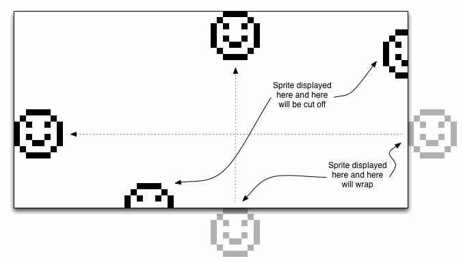
Secondly, any part of a sprite that is off the right edge or bottom edge of the display will simply not be displayed. Fragments of sprites do not wrap around to the other side of the display. However, if the programmer attempts to display the entire sprite off the right edge or bottom edge of the display, it will wrap around. So setting 0x20 for the y coordinate is equivalent to setting 0x0, setting 0x21 is equivalent to 0x1 and so on. It will wrap again at all multiples of 0x20. The same will happen with the x coordinate. Setting it to 0x40 is equivalent to setting it to 0x0, and it will wrap again at all multiples of 0x40.
The timing for this routine gets a little bit complicated because it depends on a number of factors:
- how many rows the sprite has
- by how many pixels the sprite data is offset from the screen data
- how many collisions occur
- whether the sprite is partly off the right edge or bottom edge of the screen.
In terms of the time taken to run the actual code, if you ignore the case when the sprite height is zero (why would you ever want to do that?), then the shortest scenario, which is one row of sprite data, no pixel offset, no collisions, and sprite is at bottom right edge of screen is 170 cycles (771.8 microseconds). The worst case scenario (15 rows of sprite data, offset by seven pixels, collisions on every row and the whole sprite is on screen) requires a massive 3812 machine cycles (17306.48 microseconds).
That’s not the end of the story though. Just before it enters the part of the routine that actually draws the sprite to the display memory, this routine executes an IDL instruction. Effectively this tells the 1802 processor to sit around and do nothing until the next interrupt occurs. At that point the interrupt routine occurs (during which the display is refreshed). Only once control has returned from the interrupt routine does the sprite drawing routine continue and draw the sprite to screen memory. The best case scenario for this is that the interrupt occurs immediately after the IDL instruction has been executed. In this case it will add an overhead of around 2355 cycles (I say around because it might be slightly less than that if the general purpose and sound timers are inactive). The worst case scenario is that an interrupt has just occurred immediately before the IDL instruction. In this case the sprite drawing routine will have to hang around for almost a whole TV frame (3666 cycles or 16643.64 microseconds) before it can continue.
You may be wondering why it’s necessary to wait for the screen refresh at all. Why not just write the sprite to the display memory as soon as possible and then carry on? The answer is to avoid an effect known as sprite tearing. If the sprite display routine is allowed to write to the display memory whenever it wants, there are going to be occasions when the screen refresh interrupt occurs while the sprite routine is midway through drawing. If you are erasing a sprite then a portion of the bottom of the sprite will still be on screen when the refresh happens, and if you are drawing a sprite, then only a portion of the top of the sprite will have been drawn when the refresh happens.
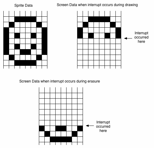
Now it’s true that by the time the next refresh comes around the sprite will have been completely erased or drawn – and that will be just one sixtieth of a second later. So you might be thinking – how would anyone ever notice the defect in that short space of time? But what actually happens is that sprite erasing/drawing gets interrupted so often that it causes a very noticeable jitter, which can spoil the user’s experience of games and other applications quite considerably. The solution, as we’ve seen, is to wait until a screen refresh has just finished and then draw or erase the sprite. After a screen refresh, about 1313 cycles (a few more if timers are inactive) will occur before the next screen refresh begins. In the worst case scenario, the sprite display routine requires 954 machine cycles to complete its work, so we can be sure that erasing or drawing will be finished before the screen is refreshed again.
A contemporary interpreter must support this instruction. However, the strategy adopted is going to depend on the graphics hardware of the target platform. It’s likely that a contemporary interpreter’s sprite drawing routine will be a lot simpler than this one as most programmers now will be able to work with display hardware that is significantly more sophisticated than that supplied with the COSMAC VIP.
Be First to Comment