This is part of a series of posts analysing the Chip-8 interpreter on the RCA COSMAC VIP computer. These posts may be useful if you are building a Chip-8 interpreter on another platform or if you have an interest in the operation of the COSMAC VIP. For other posts in the series refer to the index or instruction index.
INSTRUCTION GROUP: EX9E
Skip if VX = current key press.
INSTRUCTION GROUP: EXA1
Skip if VX ≠ current key press.
INSTRUCTION GROUP: FX0A
Wait for a keypress and store the value in VX.
The COSMAC VIP is equipped with a hexadecimal keypad with the following layout:

Chip-8 provides three instructions for responding to input from this keyboard. EX9E and EXA1 are intended for situations in which the keyboard must be read without interrupting the main programme flow, real-time games for example. I analysed these instructions in an earlier post on skip instructions.
The final instruction, FX0A, is intended for situations in which you want to wait for a key press – turn-based games for example. This instruction is part of the FXXX instruction group, so it is subject to an additional stage of decoding. I explain this in an earlier post.
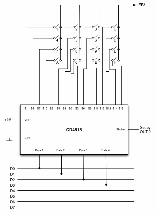
The keyboard on the COSMAC VIP is interfaced to the CPU via a CD4515 latched, four-to-sixteen-line decoder. An OUT 2 instruction will deposit a key code on the data bus and the four least significant bits of this will be latched into the decoder. The 4515 will decode this 4-bit value and pull the corresponding output line low. Each of these lines is connected to the external flag line EF3 via one of the keys on the keyboard. If the key is pressed, completing the connection, then EF3 will also be brought low. The output lines are mapped as you would expect, with 0 through 9 representing keys 0 through 9 and 10 through 15 representing keys A through F. This is shown in the simplified logic diagram below.

To scan for a key press, it is therefore necessary to cycle repeatedly through the key codes testing each one until a key press is detected. Because the 4515 is only connected to the four least significant bits of the data bus, it is not necessary to mask the four most significant bits of the value placed on the data bus. Instead a full 8-bit value can be used and decremented or incremented after each test. The 4515 will read one cycle of an 8-bit value as 16 cycles of a four bit value.
Because the mechanical key switches are wired directly to the EF3 line, the VIP’s keyboard will exhibit a problem known as bouncing. As the key is pressed then released you rarely get a perfect on and then off connection. Instead, as the contacts in the switch are being moved together or pulled apart a connection may be made and broken several times over a few milliseconds until it settles into its final on or off state. This can lead to spurious readings or noise on the EF3 line. This is combatted by including a short delay after reading the key before checking for its release.
The code for this function in the interpreter is quite simple, because it uses a routine in the ROM to do most of the work. It simply calls the keyboard reading function in the ROM. This returns the value of the pressed key in the accumulator and this is then stored in VX. Here’s the code:
Labels | Code (hex) | Comments |
FX0A: | F8 81 | 0x81 is the high-order byte of the address of a routine in the COSMAC VIP ROM that reads the keyboard. |
010C | BC | Store this in RC.1. |
010D | F8 95 | 0x95 is the low-order byte of the address of the keyboard routine. |
010F | AC | Put this in RC.0 – RC now contains the full address 0x8195. |
0110 | 22 | Decrement stack pointer – the ROM routine uses the stack so we need to ensure the stack pointer is pointing at the next empty location before calling it. |
0111 | DC | Call the routine to read the keyboard. |
0112 | 12 | Pop the unwanted key code off the stack (we already have it in the accumulator). |
0113 | 56 | Store the result in VX. |
0114 | D4 | Return to the fetch and decode routine. |
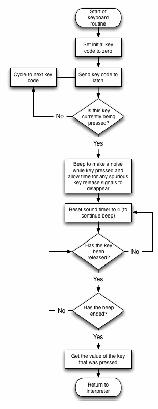
The ROM routine does the hard work of actually reading the key. The flowchart shows how this works:

Labels | Code (hex) | Comments |
RETURN_ TO_ INTERPRETER: | D3 | Return to the Chip-8 interpreter |
KEYBOARD_ SCANNING: | E2 | This is the entry point for the keyboard scanning routine. Set the stack (R2) as the register for indirect register addressing operations. |
8196 | 9C | RC.1 is used as convenient way to get a zero value for the first scan code. RC.1 is currently 0x81, but on the first pass through the scanning loop this value will be decremented, so it will start at 0x80. However, the keyboard latch reads only the four least significant bits of the value placed on the data bus, so it will effectively be read as 0x0. |
8197 | AF | RF.0 now contains the initial value for the scanning code + 1. |
KEYBOARD_ SCAN_ LOOP: | 2F | Decrement RF to get the next keyboard code (only through four least significant bits of this value will be used). |
8199 | 22 | Decrement stack pointer ready for a push. |
819A | 8F | Get the current keyboard code. |
819B | 52 | Push it on the stack. |
819C | 62 | Pop the keyboard code off the stack and use it to set the keyboard latch. |
819D | E2 | X is already set to R2, so this instruction effectively does nothing for two cycles. |
819E | E2 | See note above. These two instructions allow enough time for the keyboard latch to be set and for a valid result to appear on EF3. |
819F | 3E 98 | If EF3 is not set the key being tested is not being pressed, so loop back and try another one. |
81A1 | F8 04 | Now a key has been pressed we have to wait for it to be released, but we need a debounce delay before this is checked. The debounce delay will be a count of four on the sound timer (R8.0). |
81A3 | A8 | Set the sound timer – this will not only be used for debounce delays, it will also sound a tone while the key is being pressed. |
DEBOUNCE_ ON_ PRESS: | 88 | Get the current value of the sound timer. |
81A5 | 3A A4 | Loop back until it reaches zero. |
WAIT_ FOR_ RELEASE: | F8 04 | We will use another count of four for the release debounce. |
81A9 | A8 | Use this to set the sound timer. |
DEBOUNCE_ ON_ RELEASE: | 36 A7 B3 | Check if the key has been released and loop back if not. |
81AC | 88 | Get the current sound timer (This appears to be an error since this instruction serves no useful purpose at this point, unless it is included here simply to extend the delay in the debounce loop). |
81AD | 31 AA | Wait until the sound timer reaches zero (Q will be reset when this happens). |
81AF | 8F | Get the value of the key that was scanned. |
81B0 | FA 0F | Save only the least significant four bits. |
81B2 | 52 | Push this value onto the stack. |
81B3 | 30 94 | Branch to instruction to return to the Chip-8 interpreter |
Something to note about this code is that because the sound timer is used to effect debounce delays, this has the useful side effect of sounding a tone while the key is held down. One peculiarity about this code is that two different techniques are used to check whether the sound timer has reached zero. One is to check that the sound time has actually reached zero. The other is to check whether Q is set (as it will be reset once the sound timer has reached zero). It’s odd that both techniques are used in the same routine. In fact the ROM’s author seems to have changed his mind while he was writing the code but then not got around to tidying up his work, because in the sequence in which Q is checked there is a redundant instruction to get the sound timer value into the accumulator.
Execution time for this instruction obviously depends on how quickly the user responds, but theoretical minimum execution times are given below:
Key Pressed | Minimum Machine Cycles |
0 | 18836 (85515.44 microseconds) |
1 | 19076 (86605.04 microseconds) |
2 | 19060 (86532.4 microseconds) |
3 | 19044 (86459.76 microseconds) |
4 | 19028 (86387.12 microseconds) |
5 | 19012 (86314.48 microseconds) |
6 | 18896 (86241.84 microseconds) |
7 | 18980 (86169.2 microseconds) |
8 | 18964 (86096.56 microseconds) |
9 | 18948 (86023.92 microseconds) |
A | 18932 (85951.28 microseconds) |
B | 18916 (85878.64 microseconds) |
C | 18900 (85806 microseconds) |
D | 18884 (85733.36 microseconds) |
E | 18868 (85660.72 microseconds) |
F | 18852 (85588.08 microseconds) |
The small overhead for the second stage decoding of type FXXX instructions must be added to these figures. In reality execution times will naturally be much longer than this because nobody could physically press and release a key that quickly. Even without taking the human delay into account, these execution times are much longer than most other instructions. This is because each time this instruction is used at least 8 full frames must elapse before the routine can return because of the debounce delays.
The programmer of a contemporary interpreter should implement this instruction. They are though, likely to have an easier time of things because most modern keyboards have a hardware debounce, so there is no need to attend to this in software. Of course an added complication is that the keys 0 to 9 and A to F on a full keyboard are not placed in an optimal position for games, so you will almost certainly want to provide a means of mapping these to other keys.
Be First to Comment