This post was first published in 2013 so descriptions or images of the ARP2600V software or documentation might not be current.
The ARP 2600 is a classic analogue synthesiser. It was created back in 1971 and it’s a sound designer’s dream as just about every signal into and out of each module can be rewired with patch cables. If I had the space and the money I’d love to have a real one of these to play with. Sadly I have neither, so I’ve had to content myself with Arturia’s excellent software emulator, the ARP2600V.
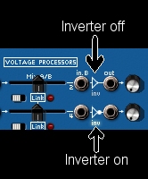
Arturia’s documentation is a little sparse in places. One of these places is the description of the Voltage Processor section of the synthesizer. If, like me, you were confused as to how the signal inverter works, here’s the answer. To invert the signal you have to click on the little signal inverter symbol between the B input jack and the output jack. This looks like an arrow head pointing towards the output jack. The symbol will then change to show a dot next to the inverter symbol. Both the symbol and the label “Inv” will light up.
Now that you know how it works, here’s a bit of fun you can have with it. You can use this device to invert the control voltage from the keyboard so that as you play from the left to the right the pitch gets lower instead of higher. To do this, first run a patch cable from the KEYB CV OUT x1 jack (this is located to the left of the keyboard) to one of the B inputs on voltage processor. Make sure you move the corresponding mix slider all the way across to the right; otherwise the signal from the keyboard will not be scaled correctly. Now click on the inverter symbol to the right of the B input jack so that it lights up. This switches the inverter on.
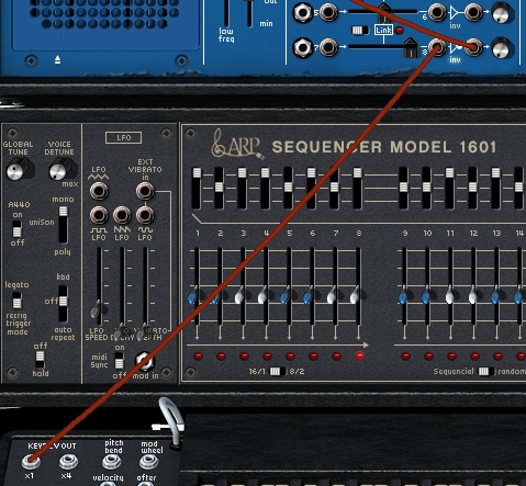
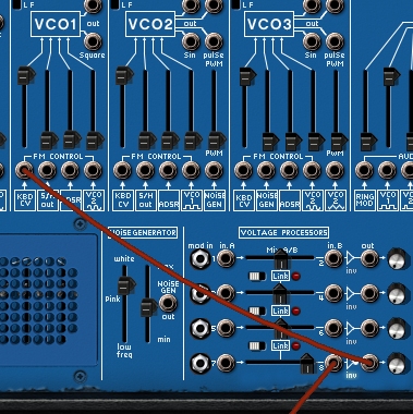
Finally run a patch cable from the output jack to one of the FM Control jacks on the oscillator you want to control. It’s probably best to use the leftmost one so that you override the pre-wired control voltage from the keyboard. Make sure that the amount slider above the FM Control jack is pushed all the way to the top.
Now try playing a simple melody on your MIDI controller. Crazy!
Be First to Comment