This post is the fourth in a series in which I attempt to build experiments from Charles Platt’s excellent introductory electronics book Make: Electronics.
You can find an index of all the posts in this series here: Electronics Index.
In this post I’m completing some switching experiments from the book.
For this experiment I’m making use of small panel switches. These have a metal flange with screw holes so they can be attached to a panel. On the reverse they have three tiny terminals. In the previous experiments in this series, I’ve been hooking components together with test leads terminating in crocodile clips. But the lugs on these switches are so small, it’s difficult to attach these leads without the clips touching and shorting out.
So, even though soldering is not introduced properly until later in this series, I’ve jumped the gun and soldered hook-up wire to the lugs on the switches to make them easier to work with. I’ve used a stiff solid core wire so I can either connect test leads using crocodile clips to the end or push the ends of the wire directly into a breadboard.
The type of switch I’m using is a single-pole, double-throw switch, which is often abbreviated to SPDT. This means you can only wire it up to a single circuit because it is single-pole, which means it has a single common terminal (the central lug on the back of the switch. And it’s double-throw because that common terminal can be connected to either of the two outer terminals by sliding the switch. This was the initial position of the switch, with the slider to the left connecting the green terminal (left) to the common terminal (centre):
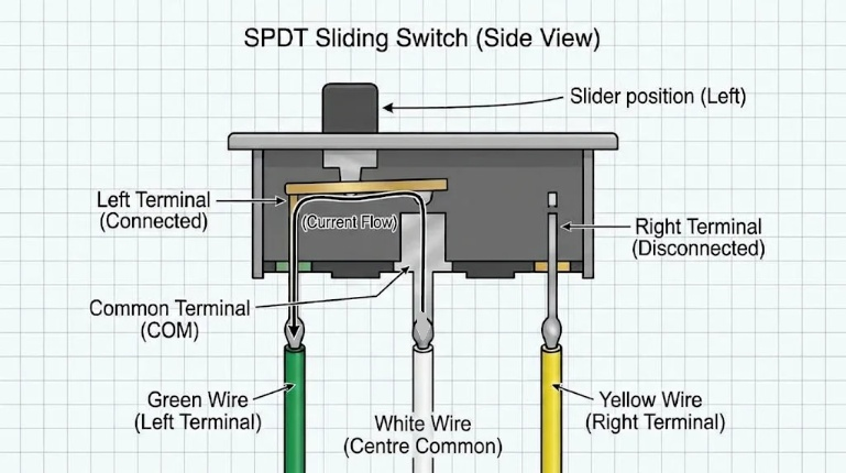
When I connect a continuity tester to the green and white terminals with the switch in this position, I get a tone indicating that current is flowing. But if I moving the slider to the opposite side, the common terminal is now connected to the terminal on the right (yellow) and disconnected from the terminal on the left (green) so the tone stops, as I no longer have continuity:
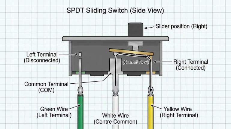
I proved this by transferring the meter lead from the green wire to the yellow wire and I once again got the tone showing that current was able to flow from the common terminal to the yellow terminal. And again, if I move the switch back to the left, the tone stops, because the yellow terminal has now been disconnected again.
There are other switch types like, for example, double-pole, double-throw (DPDT) where there are two sets of terminals so you can connect the switch to two sides of the circuit or two different circuits. Another type is single-pole, single throw (SPST) where you would only have two terminals rather than three.
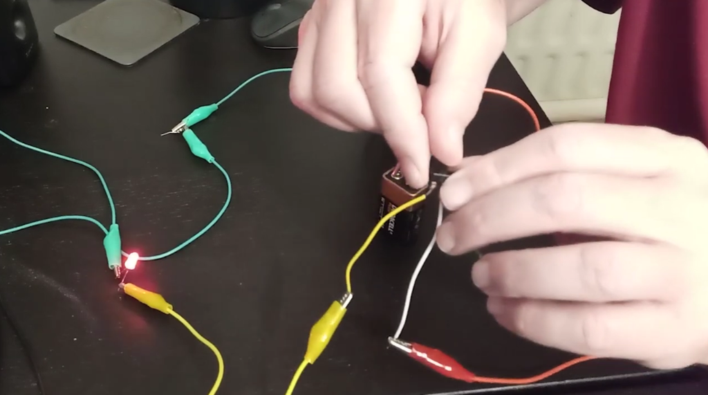
I put together a simple circuit from the book using test leads with crocodile clips. I used these to connect the positive terminal of a 9v battery to the common terminal of the switch. For this circuit I left the green wire unconnected, This meant, when the switch was over towards the green wire the circuit was effectively dead, and when it was over towards the yellow wire it was live. From the yellow wire the circuit was connected to the anode of an LED and from the cathode of the LED to a current limiting resistor and then back to the negative terminal of the battery.
Throwing the switch over to yellow side, as you might expect, caused power to flow and the LED to light up. Moving it over the green side caused a break in the circuit and the LED was extinguished.
For the next experiment I used two switches in series, again wiring up only the yellow wire in each switch. In this circuit, both switches need to be on for the circuit to work. This might not seem particularly useful, but there is a way to wire two switches that is both very useful and commonly found in lighting circuits in homes.
If you live in a property that spans two or more storeys or floors and these are connected by a stairway, you may have encountered the situation in which the light above the stairway can be toggled on or off using a switch either at the top of the stairway or one at the bottom.
This time both wires on each of the switches are connected, but the left terminal on one switch is connected to the right terminal on the other switch and vice versa.
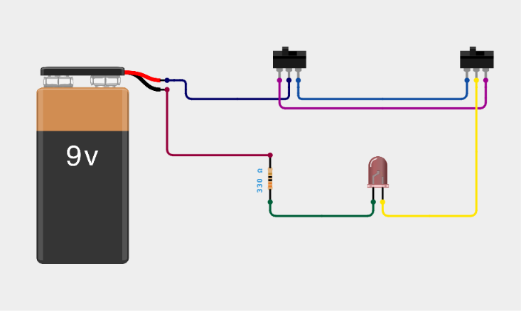
Now when the circuit is off and either switch is thrown the circuit will turn on. Now either switch can again the thrown to turn it back off again.
In the next post in this series, I’ll be exploring a type of switch that can be turned on or off by an electric current – a relay.
Be First to Comment