This post is the second in a series in which I attempt to build experiments from Charles Platt’s excellent introductory electronics book Make: Electronics.
You can find an index of all the posts in this series here: Electronics Index.
So this is a small batch of introductory experiments to introduce basic electronic components.
Resistors
A resistor is a component designed to resist the flow of current, as the name suggests, They come in a variety of values, expressed in ohms (Ω) which is a measure of their resistance. In many resistors the value is indicated with a series of coloured bands on the body. You can find details about this colour coding in Charles Platt’s book and in other sources on the web, like this Wikipedia page.
So I picked a resistor with a value of 470Ω, according to its colour bands, and measured the actual resistance with a multimeter. Resistors don’t have a polarity, so it didn’t matter which way round I connected the probes from the multimeter. I got a reading of 458Ω.
As I mentioned earlier, this resistor is supposed to be 470Ω, so does this discrepancy mean I have a faulty resistor? Well no, it;s difficult to manufacture components with a very precise value, so they’re manufactured to a tolerance, where the actual resistance is within an acceptable band of values around the specified value.
In the case of this resistor, which has a beige body, the tolerance is ±5%. So in the case of this resistor, we can expect the actual value to be between 446.5Ω and 493.5Ω. Which means my reading of 458Ω is perfectly acceptable and indicates that the resistor is not faulty.
I also had some resistors with a blue body and a tolerance of just 1%. So I measured one of these with a stated value of 150Ω, again using the multimeter. I got a reading of 148Ω. I should have got a reading of between 148.5 and 151.5. So what does this mean? Well it could be that the component falls outside the advertised tolerance – which is not beyond the realms of possibility for cheap components bought in bulk from some online stores. But, as one of my YouTube channel viewers pointed out, I’m also using a cheap multimeter and so the precision of that has to be taken into account. But either way it is always worth checking the value of components before using them in a circuit.
LEDs
I mentioned that resistors are used to resist the flow of current, but why would we want to do that? Well a good example is when we use the next component, a Light Emitting Diodem more commonly abbreviated as LED.
LEDs need a certain amount of forward voltage before they will work, beyond that voltage as the current through them increases they will gradually get brighter, but there does come a point where the current through them gets too great and the LED will be destroyed.
So limiting the current through the LED to ensure that doesn’t happen is a good example of an application for resistors. To do this, we put a resistor in series with the LED. The value of the resistor will determine (a) whether the LED is adequately protected and (b) how bright the LED will be.
So, as I was planning to follow the experiments in the book to test an LED to destruction, I put on some safety glasses. The chances of an LED actually exploding is very slim, but it’s always good to err on the side of safety in these experiments.
In the experiment I had a 9V battery in series with a red 5mm LED and a resistor. Unlike resistors, LEDs do have polarity, so it’s important to connect them the right way round. The way you can tell is that one of the leads is slightly longer. This is the anode, that is connected to the positive side of the circuit. On some LED bodies, the rim around the bottom of the LED has a slighly flattened edge above the other lead, the cathode, which is connected to the negative or ground side of the circuit. Connecting an LED the wrong way round can also cause it to be destroyed.
I started by connecting a 1.5 kilohm (kΩ) resistor (that’s 1,500Ω) in series with the LED. This provided adequate protection but a low level of brightness.
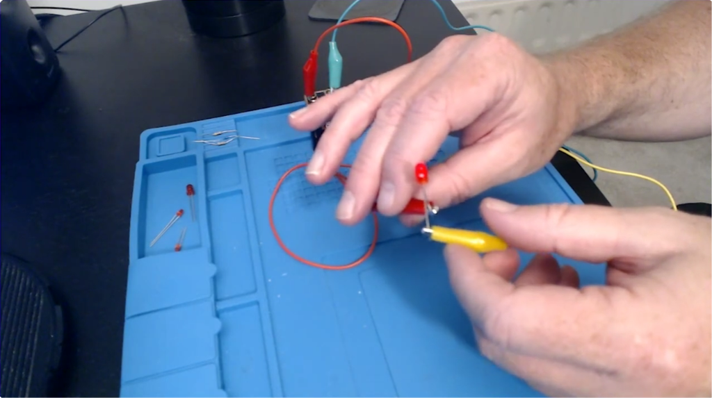
I then tried a 470Ω resistor in series with the same LED. This also protected the LED and resulted in a higher level of brightness.
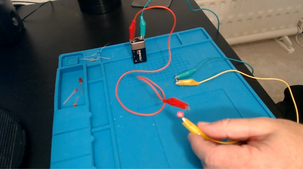
Then I tried with a 150Ω resistor. This also worked and, as you might expect, the LED was even brighter.
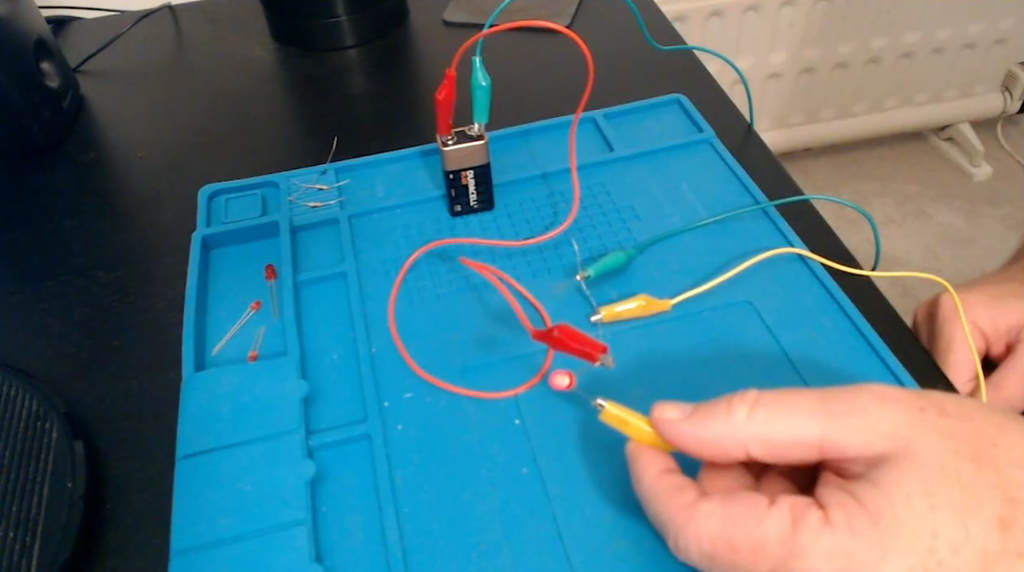
Finally I tried it with a 15Ω resistor. Amazingly the LED managed to cope even with this very low level of protection.
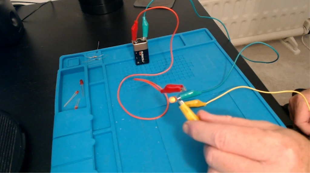
Finally I tried connecting the LED directly to the battery and it died instantly. I confirmed this by connecting it again via one of the resistors and found that, as expected, it no longer worked.
The book suggests that smaller LEDs tend to be more sensitive, so I tried the experiment again with a 3mm red LED and a 150Ω resistor. It was very bright.
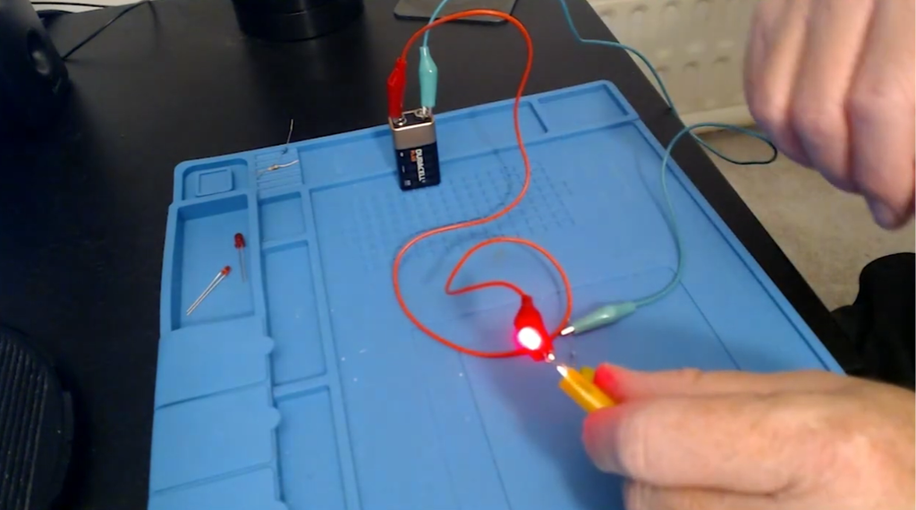
With the 15Ω resistor, this 3mm LED flickered on briefly, then died. The experiment shows how easy it is to kill LEDs if you don’t include protection with an adequate resistor.
The next experiment was to put a multimeter in series with the LED and resistor to measure the current through the circuit. With a 150Ω resistor and 5mm red LED i measured about 43 milliamps (mA). With the 470Ω resistor I measured about 15mA.
As a side note, when handling the 150Ω resistor during this experiment, it was hot enough to burn my finger, while the 470Ω resistor remained cool. The reason the lower valued resistor got so hot is that some of the electrical energy is being converted to heat. Resistors have another rating, which is the amount of power they can dissipate. The ones I used in this experiment can dissipate a maximum of a 1/4 of a Watt. The 150Ω resistor was dissipating about a 1/5 of a Watt, so close to its maximum level, which explains why it was so hot.
Fuses
This side effect of resistance can actually be a very useful feature and is the basis of the heating elements in many household appliances, such as electric fires and hair dryers. It’s also the property that enables fuses to protect circuits from too much current.
A fuse is just a piece of wire running through a hollow body between two terminals. The wire will conduct electricity provided that the current flow is below the rating of the fuse. If the current exceeds that rating, then the wire will become too hot and melt, thus breaking the circuit and potentially preventing harm.
So I ran some experiments from the book to test this theory. I started with a 1A fuse. For each fuse, I tested it first with a continuity tester to ensure it was intact and conducting electricity.
I then connected the fuse directly to a 9v battery. The wire lit up briefly and then melted. This was confirmed by applying the continuity tester again.
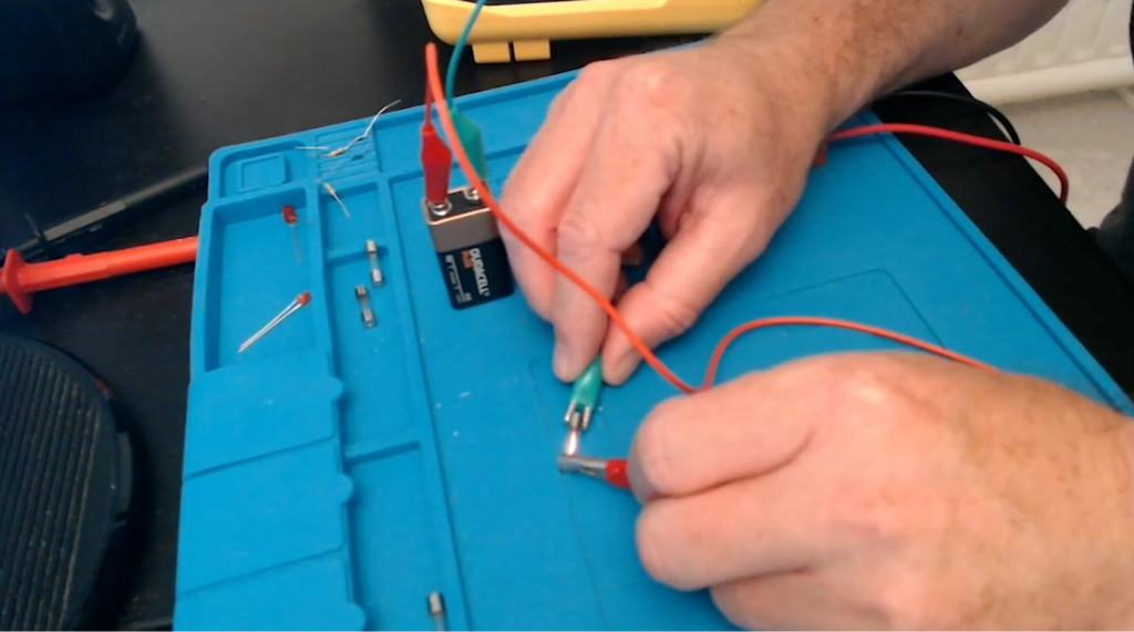
A 3A fuse connected to the battery also blew very quickly.
A 5A fuse though was able to withstand the current from the battery and was still intact when testing again with the continuity tester. So I could conclude that the current drawn from the battery was somewhere between 3A and 5A.
Addendum
In an addendum to this experiment, I measured the voltage in different parts of the circuit.
Measuring the voltage across the battery terminals, I got 9.39 volts. Of that 7.18 volts were dropped across the resistor and about 2.19 volts was measured across the LED. Note these figures don’t add up exactly because there’s always a loss of some precision in the measurement. What it does show though is the most of the voltage from the battery is dropped across the resistor.
[…] Make: Electronics Book Experiments 2 to 4 – LEDs, resistors and fuses […]
[…] Make: Electronics Book Experiments 2 to 4 – LEDs, resistors and fuses […]