This post is part of a series in which I attempt to build experiments from Charles Platt’s excellent introductory electronics book Make: Electronics.
You can find an index of all the posts in this series here: Electronics Index.
In this post I learn all about the humble capacitor.
n the previous post in this series, I made use of an electrolytic capacitor. Many types of capacitor have no polarity so, like resistors, they can be connected either way round in a circuit. The electrolytic capacitor does have polarity so, like an LED, you need to connect it the right way round to avoid damage. Also, like LEDs, they have one lead that is longer. This is the anode and must be connected to the positive side of the circuit. The shorter lead goes to the negative side and that’s reinforced because the body of the capcitor has a stripe with a minus (-) sign printed above that lead.
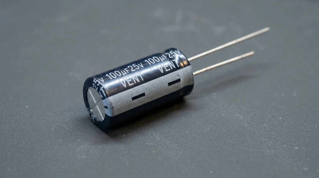
I like to think of capacitors as a counterpart to a battery, because whereas a battery generates an electric charge, a capacitor stores an electric charge.
I built the first circuit in the book, which has a capcitor being fed power to its anode from a 9v battery via a momentary push button and a resistor. Also connected to the anode of the capacitor is an LED in series with current limiting resistor, which then returns to the negative terminal of the battery. The cathode of the capacitor is connected to a resistor and another momentary push button swith, then, again, back to the negative terminal of the battery.
When the button in series with the capacitor’s anode is pushed, the capacitor begins to charge and, as it does so, the LED illuminates and becomes gradually brighter, reaching maximum brightness when the capacitor is fully charged.
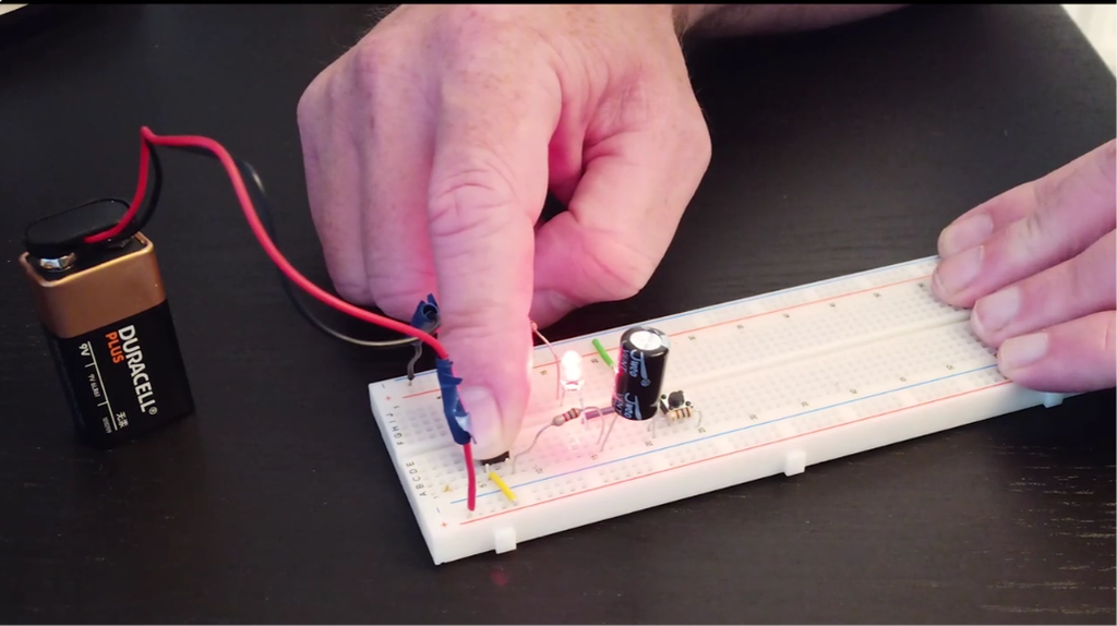
When the button is released, the capacitor will slowly discharge and the LED gradually becomes dimmer and eventually goes out. This happens more slowly then charging. I can repeat the cycle by pressing the button to charge the capacitor again.
If, after charging the button, the second button is pressed, this will cause the capacitor to discharge very quickly and the LED will go out instantly.
As well as storing charge, another important charactertistic of capacitors is that they block direct current (a current which flows only in a single direction).
This can be demonstrated with a second circuit. This makes use of a second type of capacitor, a ceramic capactor. This type of capacitor is not polarised and can be connected either way round in a circuit.
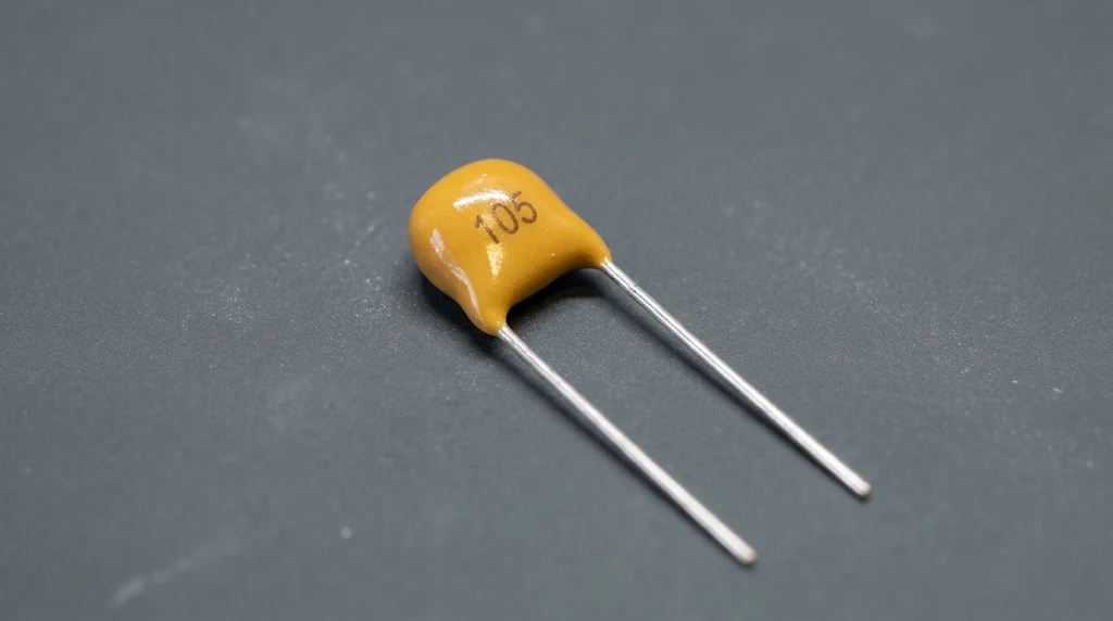
The circuit, from the positive terminal of the battery, runs through a resistor, the ceramic capacitor, a multimeter set to measure current, and then back to the negative terminal of the battery.
Connecting the battery shows no current flow on the meter, proving the capacitor is blocking the flow of direct current.
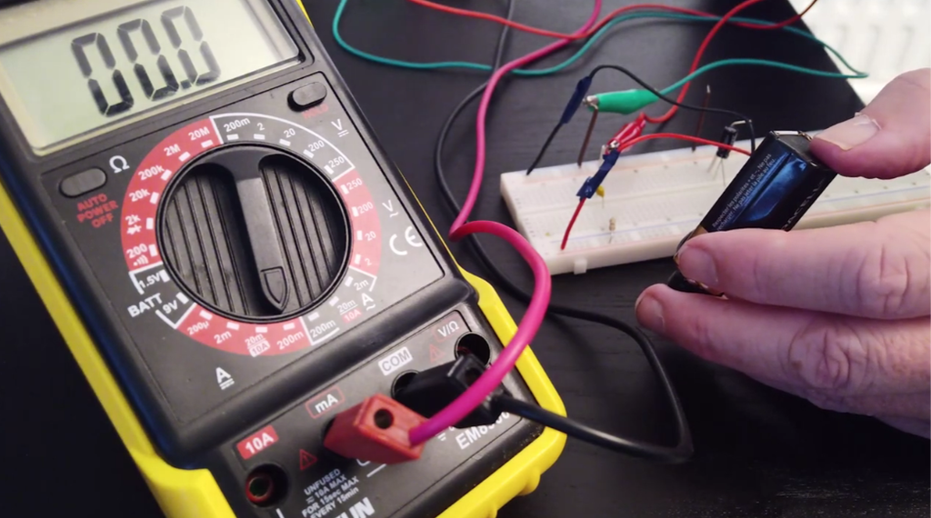
I repeated the experiment, this time with a higher capacity electrolytic capacitor. In this case, because the capacitor takes longer to charge, I could see a small current flow as it was charging, but this quickly reduced to zero.
You might be wondering what the resistor in series with the capacitor does. Well the value of the resistor will affect the time taken for the capacitor to charge. I set up another experiment from the book to demonstrate this. This experiment first required me to measure the battery voltage, which I did, getting a reading of 9.23v.
The measurements will be made with a 1000μF electrolytic capacitor. The circuit has buttons allowing the capacitor to be charged and discharged via resistors. There are also a couple of wires that can be used to short the capacitor leads to cause it to instantly discharge. These leads are then connected to the multimeter to measure voltage across the capacitor.
I timed how long it took the capacitor to charge from 0v to 9v and how long it took to discharge down to 0.1v. These were the resuls I got with two different values of resistor.
Resistor value | Charge time to 9v | Max. full charge voltage | Discharge time to 0.1v |
1kΩ | 5.92 secs | 9.21v | 7.21 secs |
10kΩ | 56 secs | 9.07v | 1 min 4 secs |
The book does not make use of oscilloscopes in any experiments, which is the right decision, as the author clearly wants to keep the experiments affordable for as many people as possible. However, I am a very visual thinker and respond far better to a graph than I do to a table of numbers. It’s difficult to get some intuition from tables of numbers, such as answering the question “is the charging rate linear?” To be fair, the book does illustrate this with static illustrations, but I wanted to see for myself, so chose to use an oscilloscope.
What the oscilloscope shows is that the charging rate is not linear.
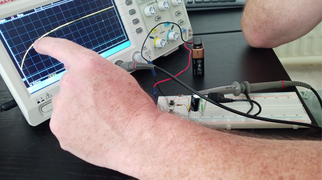
The closer the voltage across the capacitor gets to the supply voltage, the more the charging rate slows down, eventually flattening out. A similar effect can be seen when the capacitor discharges – the discharge rate slows as it approaches zero volts.
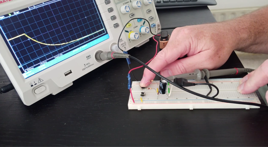
For this reason a time constant for a resistor capacitor (RC) circuit is expressed as the time taken to get from 0v to 63.2% of the supply voltage when charging and from max volts to 36.8% of the supply voltage when discharging.
So where might we use a capacitor? One application is shown by building a simple LED circuit with a push button to control power to the LED. Pushing the button closes the circuit, so the LED lights up and releasing the button opens the circuit so the LED turns off.
If I press and release the button quickly and repeatedly, the LED flashes to mirror the movement of my fingers.
I then add a 100μF electrolytic capacitor between the anode of the LED and ground. This time when I press the button repeatedly to try and flash the LED it stays on and the fluctuations are less noticeable. This is because the capacitor takes time to charge up and then to discharge, and this smooths out the signal to the LED. While a slow frequency of changes is still visible, there’s an upper limit to the frequency of changes beyond which they are no longer visible.
The final experiment has a 1000μF electrolytic capacitor with the same switches to charge and discharge, This time though, the LED is connected to the cathode of the capacitor. Now, when I press the button to charge the capacitor, the LED lights up but then quickly fades away.
Pressing the charge button again, when the capacitor is fully charged, does not illuniate the LED again. To see the LED light up again, it is necessary to first discharge the capacitor. This ability for current to flow from the negative plate of the capacitor while the capacitor is charging is known as capacitive coupling.
In the next post, I explore another type of electronic switch, the transistor.
[…] Make: Electronics Book Experiment 9 – All about capacitors […]
[…] Make: Electronics Book Experiment 9 – All about capacitors […]