This post is the fifth in a series in which I attempt to build experiments from Charles Platt’s excellent introductory electronics book Make: Electronics.
You can find an index of all the posts in this series here: Electronics Index.
In this post I explore an electronic switch – the relay.
The mechanical switches I looked at in the previous post in this series might not be the most exciting of components, but the type of switch I’m looking at in this post is more interesting – it’s the relay. Unlike manually operated switches, this switch can be operated automatically by applying a current.
As you’ll know if you viewed the previous post in this series, a single pole double throw (SPDT) manual switch has three terminals – a central common terminal and two outer terminals. Either one of the outer terminals can be connected to the common terminal at any time based on the position of the switch.
The relay I’m looking at initially looks more complicated because it has an array of 8 pins on the bottom. Ignoring the 2 pins isolated at the far end of the case for the moment, the six pins grouped at the other end of the case are two pairs of duplicated pins because each has a common pin and then two other pins to which the common pin can be connected based on the position of the switch.
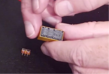
The reason there are two sets of these pins are that this relay is an example of a double-pole switch, which means you can connect it to two circuits or two parts of the same circuit. So let’s ignore the pins on one side, and the three remaining pins on the other side correspond to the three pins on the manual switch from the previous episode. The difference is the ordering, because the common pin is at one end and not in the middle of the two output pins.
But this begs the question, how do you switch the connection between the two output pins? This is where the remaining two pins on the base of the relay come in. The two isolated pins are connected to a relay coil. This is a magnetic coil that can deflect a connector inside the relay from one set of output pins to the other. So when we apply power through these pins, the relay coil will be energised and will deflect the contact connected to the common terminal from one of the output pins to the other.
To test the relay I built a circuit with a 9v battery in series with a latching push button switch – this is a type of switch that stays depressed when you push it in and needs to be pushed again to release it. The book actually suggests you use a momentary pushbutton switch, which only remains on while you hold the button down.
I connected the other side of the switch to one side of the relay coil and the other pin from the relay coil back to the battery,
With this circuit in place, pressing the push button switch causes the relay to energise and the contacts to switch from one set of terminals to the other. When I held the relay up to my ear and made and broke the circuit to the relay coil repeatedly, I could hear the contacts clacking as they moved from one side to the other and back again.
I next connected a continuity tester between the common terminal on one side of the relay and the normally open terminal on the same side. As you might expect, the continuity tester emitted no tone because there was no current flowing, but as soom as I pushed the button switch, the relay coil was energised, causing the contacts to deflect and the continuity tone was heard.
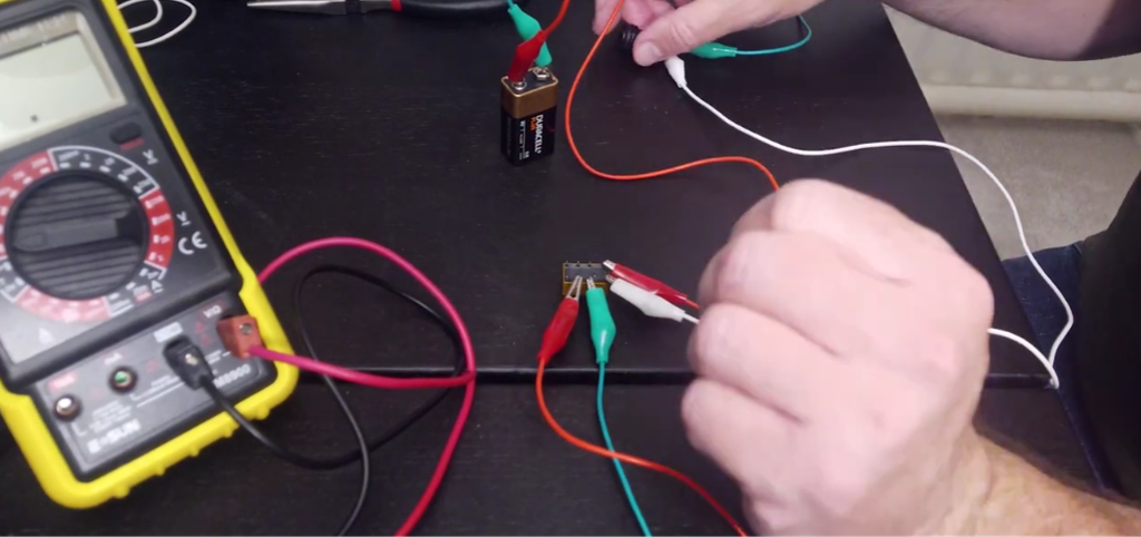
When I now transferred one of the continuity tester’s probes from the normally closed to normally open terminal, then the continuity tone ended because, of course, the coil was still energised so the normally closed terminal was unconnected. As soon as I released the push button, then the coil was de-energised, the contact moved back to the normally closed terminal and the continuity tone was heard again.
There are some larger relays that often come with transparent cases, so you can see how they operates, but these smaller PCB mounted relays have opaque plastic cases. The book suggests opening one up to take a look inside. To do this, you take a craft knife and carefully start shaving plastic along the edges of the container.
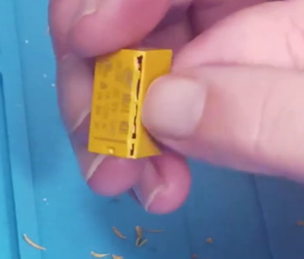
Unfortuantely, even when all the outer plastic is removed, there’s still not much to be seen with this type of compact relay. But I was able to see the copper contacts moving up and down as the relay coil was energised and de-energised.
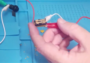
It normally wouldn’t be a good idea to use an exposed relay like this in a circuit, as it is no longer protected from dirt, dust and moisture. It will be fine to use for this one experiment though.
I built a circuit from the book in which both the normally open and normally closed contacts are each wired in series with an LED and the coil contacts are wired in series with a momentary push button. When I applied power to the circuit, the LED connected to the normally closed contact lit up, while the other LED was dark. But if I activate the push button, the relay coil is energised, the common terminal is now connected to the normally open contact and the second LED lights up while the first one goes out.
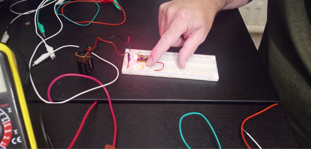
Likewise, if I release the button the lit LED goes off and the other LED is lit and I can now oscillate between the two by repeatedly pressing and releasing the button.
The book suggests a modification of this circuit in which the push button is now in series with the normally closed contact. What happens with this configuration is that depressing the button caused the relay to energise and connect the common contact to the normally open contact. But this then breaks the circuit to the coil so the coil is de-energised and the common contact switches back to the normally closed contact. As long as I hold my finger down, this change happens repeatedly.
While the button is held down, I could hear a loud buzzing from the relay – this was the sound of the contacts oscillating rapidly. The other side effect is that you don’t see the LED wired to the normally closed contact lighting up fully because it only ever recieves power for a very small fraction of the time, so a dim flicker is the best you can hope for. Note that this experiment is not very healthy for the relay and would eventually cause it to fail.
The book suggests one final modification which is to add a 1000 microfarad electrolytic capacitor. These components will be explored in more detail in a forthcoming experiment, but suffice it to say that the effect it has is to slow down that feedback loop, so now the relay coil stays energised for longer and we get a cycle thats slow enough for the second LED to light up.
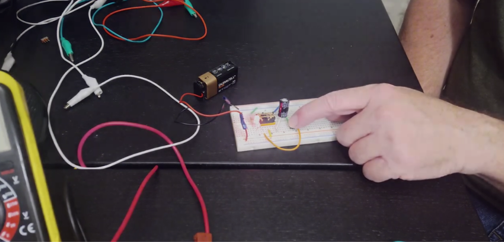
In the next post in this series, I’ll be revealing why the capacitor had that effect on the circuit.
Be First to Comment